Building the Semi-Automatic Vickers
When the Vickers was designed, British gunmaking had a strong legacy of handicraft. This was contrasted with American gunmakers, such as Browning, which engaged in and designed for mass production. The implication is that the Vickers design was hand-assembled and many parts were intended as "file to fit" on assembly. This is one of the problems that Colt needed to overcome to meet the WWI production goals. While it is debated as to the degree of interchangeability of parts, like other European weapons of the era, key pieces were serial numbered to its individual gun thus cutting down on the necessity of absolute interchangeability. In other words, dimensions may vary from similar parts to similar parts. I have found this to include some noncritical dimensions of the outside side plates. On a positive note, most Vickers parts kits available today are of Australian origin and the Lithgow factory seems to have have achieved very close tolerances if not complete interchangeability.
Modified Components of the Semi-Automatic Vickers
The semi-automatic Vickers is based on the design of the Vickers machinegun. However, the semi-automatic receiver has
been originally designed and manufactured to permit only semi-automatic fire.
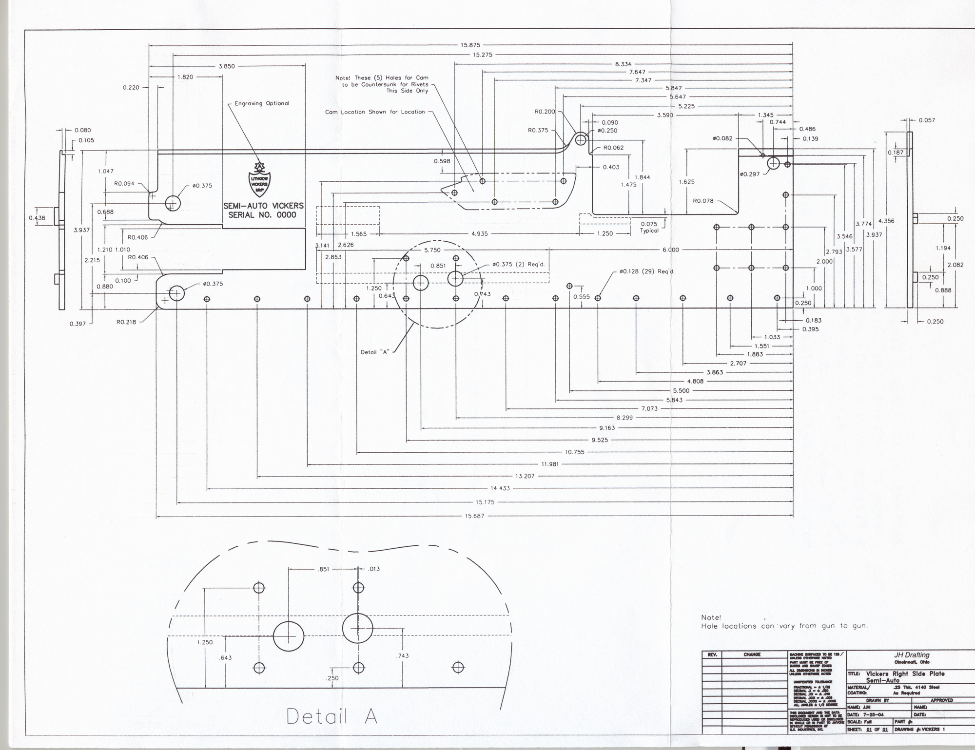
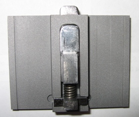
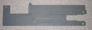 The semi-automatic right outside side plate (Note: You might want to investigate the nomenclature page for parts names) has been manufactured with two integral steel rails protruding from the inside of the plate into the receiver box cavity. These rails prevent the installation of standard Vickers machinegun recoil plates (also called side plates - yes, this can get confusing). The above right (outside) side plate on the right shows the steel rails. This plate was supplied by Halo Manfacturing in Oregon and purchased through an FFL dealer. An important note; the semi automatic right side plate MUST be used with the “denial island” (see below) for the gun to be considered semi automatic. Additionally, the denial island must be welded in place. I recommend that the denial island be welded in place between the side plates immediately after attaching the right side plate. Below are the dimensions of the semi-automatice right side plate.
(Click to see a larger image)
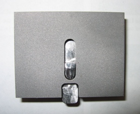
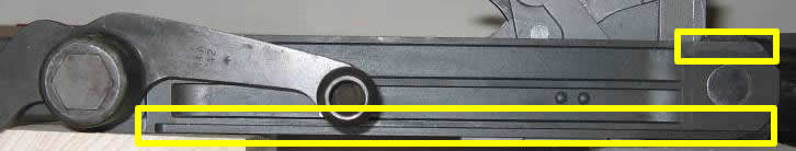 The two outlined areas in the image show the necessary modification to the right recoil plate to permit it to slide inside the receiver cavity when the semi-automatic right side plate is used.

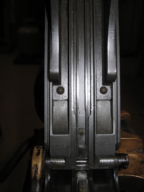
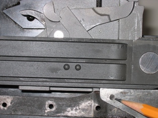
Looking into the receiver box with the rear top cover open, the picture shows the recoil plates in position inside the receiver box. The rails which are part of the right side plate and project into the cavity prevent the installation of standard Vickers machinegun recoil plates (also called side plates).
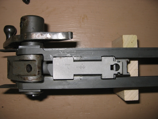 In addition to this, the opening for the lock in the recoil plates have also been modified to prevent the easy installation of a standard Vickers machine gun lock. You can also see the groove machined away from right recoil plate (The picture shows both the right and left recoil plates. The right recoil pate is the top plate) to permit it to slide into the receiver cavity with the new right side plate.
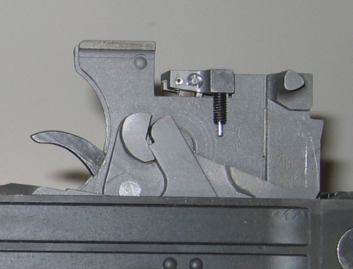
A Vickers machinegun lock assembly is significantly redesigned by machining away an area approximately 1 5/8 inches in length by 3/8 inch deep from the front upper area of the lock body. The extractor has also been reduced in height. A pivoting and sliding sear plate has been attached to the sear and is located in the machined away area. The lock modifications seen here were completed by Lonnie Ingram, Batavia, Ohio. The lock on the left shows the sear in the up position ready to be engaged by the firing linkage contained in the denial plate. The lock on the right shows the sear in the down position.

.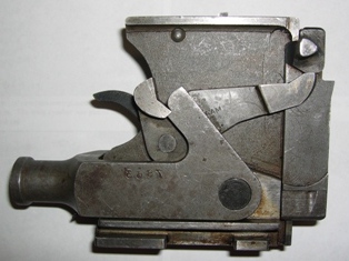
Above is an unmodified lock.
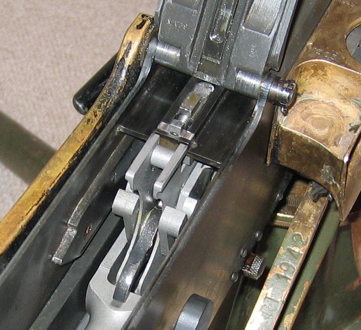 A steel plate, often called the "denial island", is welded to each side plate in the area of the top cover hinge to prevent using an unmodified lock. This island must be welded in place to conform to the BATF approval letter. This island contains a sliding firing linkage. This sear plate slides under the denial plate as the lock moves forward and tilts upwards to engage the sear linkage. The denial island in this picture was supplied by Lonnie Ingram.
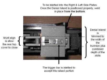
Two pictures of the denial island before being installed. The picture on the left is the top of the island and the picture on the right is the bottom of the island.
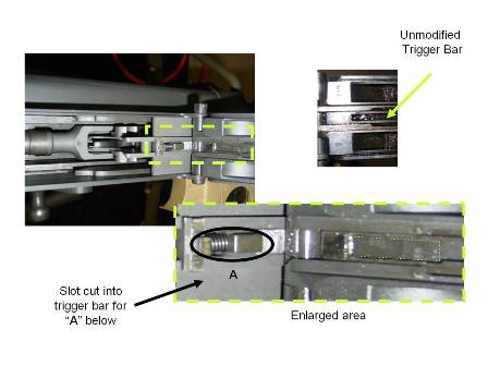
 The original Vickers trigger bar that runs the length of the rear top cover is modified to accept the denial island's sliding firing linkage stud that trips the sear when the trigger is pulled.
Building with Rivets
I suggest removing the water jacket when completing the assembly; this is necessary to set the blind rivets. Some current day builders have successfully used screws to eliminate removing the jacket and instructions on assembly using screws is found at http://www.projectguns.com/vickers.html. The general sequence when removing the water jacket is:
1. Remove the trunnion from the water jacket.
In my experience, removing the water jacket is best done by two people. The first step is to make a wrench with two brass lugs that fit into the muzzle gland and water tube holes on the front of the jacket.  This was not how it was done at the factory, but it works.
Make a witness mark across the jacket and trunnion for reassembly. Clamp the trunnion into a vice using blocks to prevent damaging the trunnion and place wet cloths on the trunnion to prevent overheating. Remove the water plug. Apply heat and unscrew the rear stud for the water plug chain (IMPORTANT!); next heat the trunnion at the intersection of the water jacket. This requires something other than a hand-held propane torch. A Mapp torch works but a wide torch attached to a large propane tank also seems to work quite well. It does not take a high temperature to melt the solder; it takes a great deal of heat over a broad area. When you see the solder ooze, have your helper keep applying the heat and begin to unscrew the jacket.
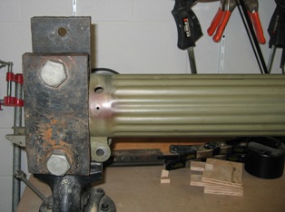
It's probably overkill, but I use two large steel blocks to clamp the trunnion before heating and unscrewing the water jacket. My intent is to keep the pressure on the forward portions of the trunnion to eliminate any possibly of twisting the trunnion.
2. Drill the rivet holes in the right side plate.
3. Mount inside cam on the right side plate and check lever bracket. The check lever bracket and must be riveted before mounting the Right Side Plate.
4. Temporarily assemble (including grips, top covers, barrel, recoil plates, lock) to locate the denial plate. Mark the location for milling the slot to mount the plate.
5. Disassemble and mill grooves in Right & Left Side Plates for the Denial Plate;
trim the width of the Denial Plate as needed.
6. Assemble side plates to the trunnion; spread solder paste, and rivet. Be sure to include the knob (rivet) for the Fusee Spring cover. Heat to solder the plates to the trunnion. Contrary to the Projectguns tutorial, please note that the right and left outside side plates (also, properly called the outside casing) must be attached before the bottom plate. The rivet in the below picture cannot be completed with the bottom plate riveted in place as the ProjectGuns.com tutorial suggests.
7. Assemble the lower plate to the side plates; spread solder paste and rivet
8. Reassemble and install denial island. Inlet trigger bar and test function.
9. Weld the denial island in place from the bottom.
I have found it necessary to do a small amount of hand fitting after the final assembly. I don't know if the need for the hand work is because of a small variation in the trunnion alignment or variations in part dimensions. Most of this work involves getting smooth functioning between the outer receive box and the inner side plates (recoil plates). The goal is to have the internal part freely move with less than 4 pounds of force (see Building > Weighing the Recoiling Portions).
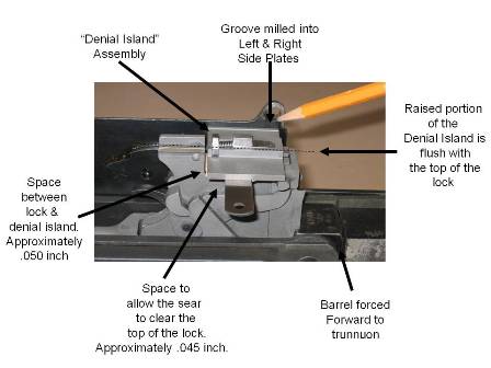
Fitting the Denial Island
The proper fit of the denial island is critical for proper functioning. The below pictures give the approximate positioning of the island with respect to the lock.
Fitting the Crank Lever
The downward blow of the crank group must be taken by the crank stops on the recoil plates. If the crank lever makes hard contact with the stop during firing, the crank will beat the check lever rivets out of the sideplate. Goldsmith (p. 554) provides the following method:
To ensure that this is being done remove lock from gun and let crank handle forward slowly. A feeler of 1 1/2 thousandths thickness (or a piece of tissue paper) should be gripped between the crank and crank stops. At the same time there should be a clearance between the crank handle and the check lever and between the tail of the crank handle and the roller, thus ensuring that none of the shock is being taken on these components. The clearance between the crank handle and the check lever should be .005 in or "note-paper clearance" and the same clearance should be obtained between the tail of the crank handle and the roller. If these clearances are insuffident they should be adjusted by removing metal from the check lever and the tail of the crank handle respectively. The front of the crank handle and the roller must never be filed.
An alternate method is to set the headspace so that with a go gage or sized empty case in the chamber you feel the "check" just prior to the crank handle contacting the check lever. An .005 feeler gage should slip into the gap between the handle and check lever. If it makes hard contact, with correct headspace, the check lever should have a little metal removed until you get the .005-.004 space.