Enhancements
Lonnie's Coil Spring Lock Conversion
A weak lock mainspring is the major source of misfires in the semi-automatic conversion. This is really no surprise since leaf springs in the Vickers' lock have been know as a weak point of the design. In the original Vickers lock design, the mainspring is a leaf spring placed vertically in the upper part of the lock frame, the longer end engages a boss on the firing pin and the shorter butts against and adds pressure to the sear (trigger by british nomenclature). Figure 1 shows this arrangement.
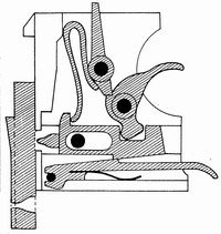
Figure 1: Original lock design.
The semi-automatic conversion uses the same arrangement but, to make space for the disconnector at the top of the lock, the spring is shortened which can contribute to a light primer strike and a failure to fire especially with hard primers. Figure 2 illustrates this shortening of the leaf spring so the lock will pass beneath the denial island.
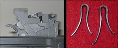
Figure 2: Semi-automatic lock (far left picture) showing how
the leaf spring must be shortened to fit under the disconnector.
The second picture shows the modified spring (second from far right)
with an original spring on the far right (Picture of springs
from http://www.projectguns.com/vickers.html)
The Czechs addressed the problem with the original design by redesigning the lock of their 7.92mm Vickers to use coil springs. The Czech design (picture from Dolf Goldsmith book. p. 373), while more complicated than the original Vickers, did solve the leaf spring issue. An added benefit, according the Dolf Goldsmith, it that it also produced higher rates of fire. A number of years ago a company in Phoenix, AZ was producing coil spring locks loosely based on the Czech design. Now, Lonnie Ingram has a coil spring conversion for the semi-automatic Vickers. While I have not tested the lock, it holds promise for solving the problem of weak primer strikes. Below are pictures of Lonnie's modification.
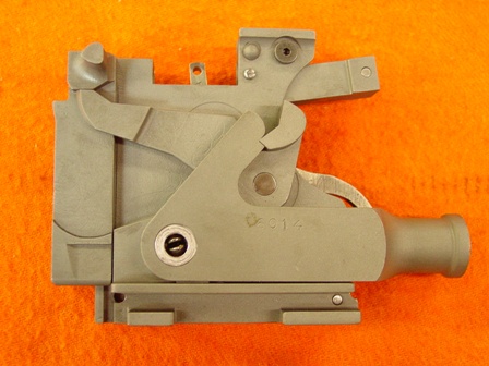
Figure 3: Left side of Lonnie's converted lock. This lock is
missing the semi-automatic disconnector. The protrusion on the
upper-right of the lock provides force to reset the sear
(picture by Lonnie Ingram).
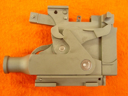
Figure 4: Right side of Lonnie's converted lock. Again, the lock is
missing the semi-automatic disconnector (picture by Lonnie Ingram).
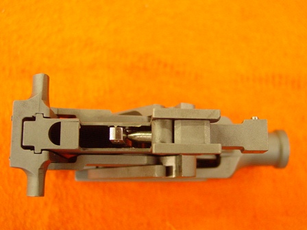
Figure 5: Top of Lonnie's converted lock. The spring loaded plunger
that tensions the sear
is visible with the semi-automatic
disconnector removed (picture by Lonnie Ingram).
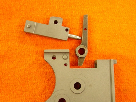
Figure 6: View of the spring loaded plunger that tensions the sear
(picture by Lonnie Ingram).
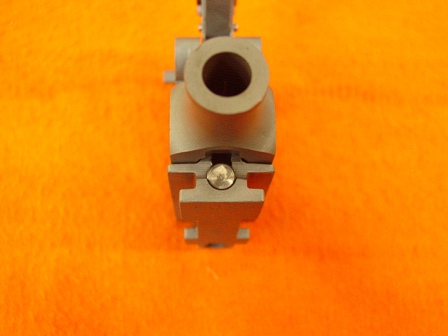
Figure 7: Rear of the converted lock. Note the plug that retains
the coil spring (picture by Lonnie Ingram).
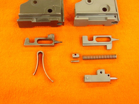
Figure 8: Comparison of unmodified SA lock body (top left), original
firing pin (middle left),
and original leaf spring (bottom left)
with the modified lock body (top right), firing pin (middle right), firing pin
coil spring plug and pin (middle right), and sear plunger (bottom right)
(picture by Lonnie Ingram).